Here’s something most project managers don’t figure out until they’re mid-renovation: there’s no universal standard for the as-built drawings procedure.
Some firms show up with a tape measure. Some send an architect with a clipboard. Some — the ones doing this at scale — deploy professional-grade LiDAR scanners and deliver verified documentation within 48 hours.
The procedure matters because the output is only as reliable as the method behind it. Drawings produced from a tape measure and a gut feeling about wall thickness will create different problems than drawings produced from a sub-millimeter point cloud. Owners, architects, and project managers receive both under the same name and are expected to use them the same way.
This guide covers the full as-built drawings procedure from start to finish — what happens at each step, where errors get introduced, and what separates documentation you can design from versus documentation that’s going to produce change orders.
Quick Answer: What Is the As Built Drawings Procedure?
The as-built drawings procedure is the end-to-end process for capturing, documenting, and delivering accurate records of a building as it actually exists — not as it was originally designed. When done correctly using LiDAR scanning technology, the procedure follows five defined steps: project scoping and proposal, site coordination and scheduling, LiDAR field scanning, point cloud processing and as-built documentation, and QA review with final file delivery. Most commercial spaces are completed within 5-10 business days from scan to delivery.
Not sure what as-built drawings are in the first place? See our guide:What Is As-Built Drawings? (Meaning + Definition)
Why the As Built Drawings Procedure Determines the Quality
The traditional approach — a drafter walks the space, records dimensions manually, and builds a CAD file from field notes — introduces error at every stage. Tape measures skip hard-to-reach areas. Notes get misread. Walls that aren’t quite square get drawn square because that’s easier. MEP runs get approximated. The result looks accurate until a contractor opens a wall.
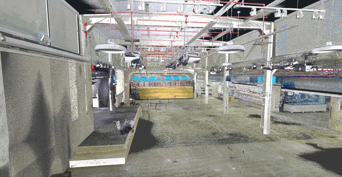
The LiDAR-based procedure eliminates those failure points. Instead of relying on human measurement and memory, it captures millions of data points across the entire space simultaneously. The CAD file is drafted from a verifiable registered dataset — not from an approximation of it.
That distinction shapes every step below.
Related: What Are As-Built Plans? (Definition + Use) — understand what the drawings represent before commissioning them.
The As Built Drawings Procedure: 5 Steps
Step 1 — Discovery & Proposal

Every project starts before anyone sets foot on site. The scoping phase defines exactly what gets documented, at what level of detail, and in what format — the decisions that determine whether the final drawings actually serve your team.
Key decisions confirmed at this stage:
- Scope — Floor plans only? Full building section? MEP included? Ceiling conditions? Exterior envelope?
- Level of Detail — A basic floor plan for leasing purposes requires less detail than a full permit submittal or Revit model for a structural renovation.
- Deliverable format — 2D CAD (DWG/DXF), Revit BIM model, PDF, point cloud, or a combination.
- Access logistics — After-hours access for occupied spaces, phased documentation for live retail, weekend mobilization for hospitality projects.
- Office standards — Layer naming conventions, title block formats, coordinate systems for multi-building campuses.
One question we ask on every project before mobilization: what are these drawings going to be used for? The answer changes everything about what we document and how. As built drawings for a tenant improvement permit look different from as built drawings feeding a full Revit base building model.
What you receive: A fixed-price proposal and full project schedule returned within one business day. No open-ended estimates. No scope creep. No change orders.
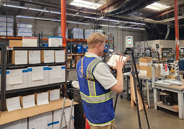
Step 2 — Site Coordination & Scheduling

With local field crews across all seven Southwest markets, we coordinate site access directly with your GC, building manager, or client contact. Occupied buildings, after-hours access, phased multi-floor projects, multi-site campuses — we handle the logistics. You don’t.
Markets served: Las Vegas · Phoenix · Los Angeles · San Francisco / Bay Area · Denver · Salt Lake City · Austin
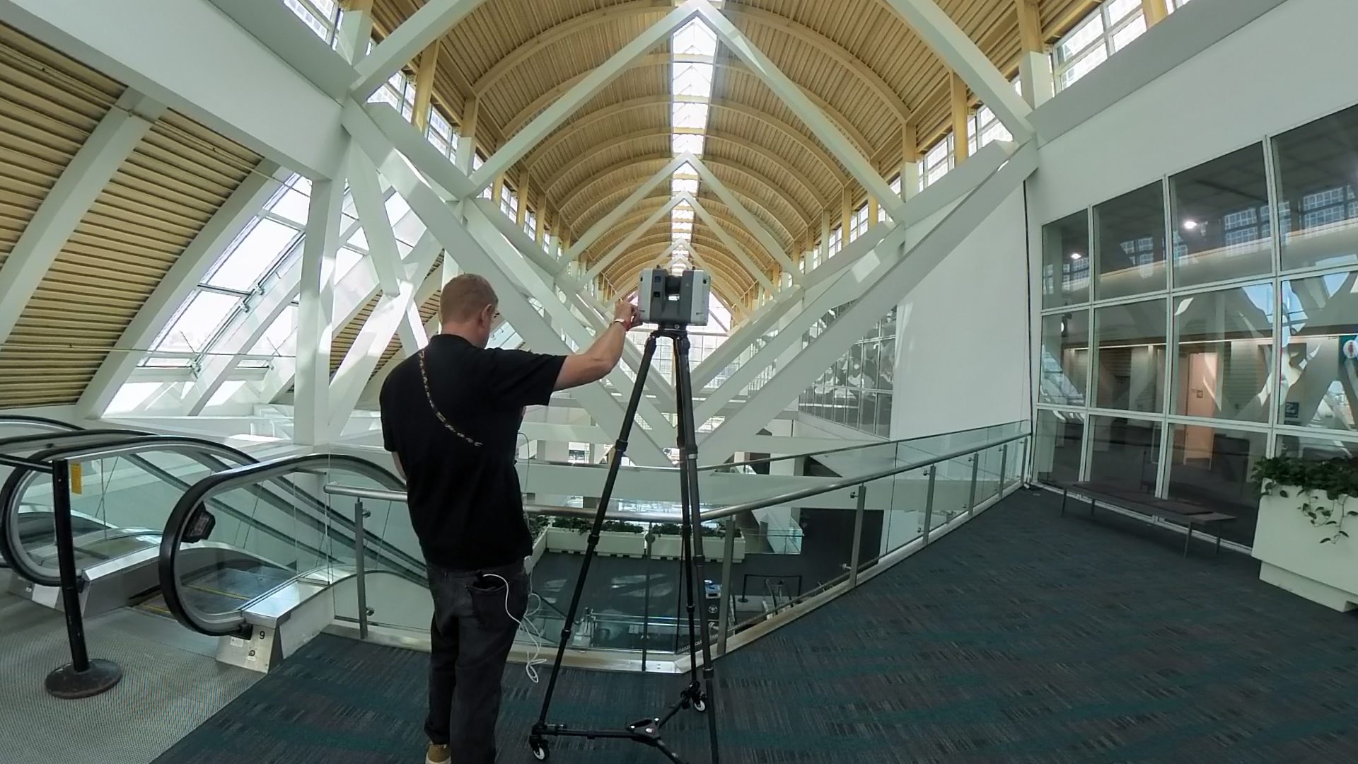
Step 3 — LiDAR Field Scanning
This is where the physical work happens — and where modern procedure diverges most sharply from the traditional approach.
Using professional-grade LiDAR scanners, our field crews set up scan positions at intervals throughout the space. Each position captures a full 360-degree spherical point cloud in approximately two to three minutes, recording the precise X, Y, Z coordinates of every surface within range — walls, floors, ceilings, columns, equipment, and MEP systems — to within ±2–3mm accuracy.
A standard commercial site scan documents:
- Interior spaces — every room, corridor, mechanical room, and utility area within scope
- Ceiling conditions — structure above, MEP routing, lighting, sprinkler heads, soffit profiles
- Floor conditions — slab variations, drains, transitions, ramps, accessible routes
- Vertical elements — columns, pilasters, shear walls, curtain wall framing
- MEP systems (when in scope) — duct runs, pipe chases, electrical conduit, panel locations, equipment dimensions
A 10,000 SF retail space typically requires 100-200 scan positions for complete coverage. A multi-story commercial building may require much more. The field scan is the most critical step — not because it’s technically complex, but because anything missed in the field cannot be recovered in the office. We plan scan positions to ensure complete overlap coverage before leaving the site. Most commercial spaces are fully documented in a single day.
Step 4 — Point Cloud Processing & As-Built Documentation
Raw scan data from each position is consolidated into a single verified, registered point cloud. This involves aligning adjacent scan positions using overlapping geometry, confirming registration error is within tolerance, removing moving objects captured during the scan, and applying high-resolution imagery to produce a photorealistic 3D representation of the space.
The registered point cloud becomes the source dataset for all downstream documentation. Unlike tape measure notes or field sketches, it can be referenced, verified, and re-queried at any point during drafting — or months later when a new question arises.
For 2D CAD deliverables (DWG/DXF): The point cloud is loaded into AutoCAD. Drafters take horizontal slice views at standard heights and trace building geometry directly from the scan — walls, openings, structural elements — to the exact dimensions shown in the data. Not approximated. Not assumed.
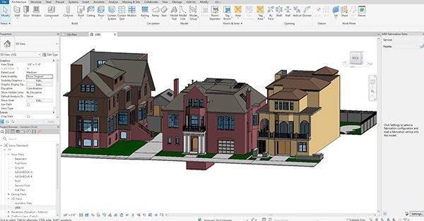
For BIM/Revit deliverables: The point cloud is loaded into Revit. A 3D model is built by placing families and system components at the locations shown in the scan data, to the agreed Level of Development.
Standard as-built documentation includes floor plans, reflected ceiling plans, interior elevations, building sections, MEP plans (when in scope), and site plan with building footprint.
Wondering how as-built drawings differ from record drawings ? See: As-Built Drawings vs Record Drawings.
Step 5 — QA Review & File Delivery

Before any file leaves our office, a second team member independently checks every drawing and model against the source point cloud — verifying dimensions, layer naming, scope completeness, and format compliance.
What QC confirms:
- Key dimensions in the CAD file match corresponding measurements in the point cloud
- All elements within scope are documented
- Layer organization follows the agreed standard (AIA CAD Layer Guidelines or client office standard)
- Drawing conventions, line weights, and title blocks meet the deliverable specification
- Coordinate alignment confirmed for georeferenced projects
Final files are delivered to a shared project folder and archived for six months, with our team available for revisions and follow-on phases.
Two-person QA. 1/2″ verified dimensional tolerance. 6-month archive.
Turnaround Times
| Project Type | Typical Turnaround |
| Single-floor retail (up to 5,000 SF) | 5-7 business days |
| Multi-floor commercial (10,000–50,000 SF) | 7-12 business days |
| Large commercial or campus (50,000+ SF) | 12-24 business days |
| Scan-to-BIM (Revit model) | 7–14 business days depending on LOD |
Rush turnaround is available for time-sensitive projects.
How to Do As Built Drawings Without LiDAR: What You’re Trading Off
It’s worth being direct about what the manual procedure looks like — because it’s still widely practiced, and it’s still what many clients receive without knowing it.
When learning how to do as built drawings the traditional way, a drafter visits the site with a tape measure, records dimensions at accessible locations, and builds a CAD file from field notes. Inaccessible areas — ceiling cavities, above-slab conditions, hard corners — are approximated or omitted. The resulting drawings reflect what the drafter was able to reach, not a complete picture of the space.
What you’re trading off with the manual method:
- Accuracy — Tape measurements introduce human error; 3D scanning does not
- Completeness — Manual surveys miss ceiling conditions, MEP routing, and hard-to-reach geometry
- Verifiability — There’s no source data to check; the drafter’s notes are the only record
- Speed — Manual surveys take longer to conduct and longer to draft from
- Repeatability — Re-querying the data later requires a new site visit
For a quick residential floor plan, manual survey can be sufficient. For commercial renovation, permitting, BIM coordination, or facility management documentation, it consistently creates problems downstream.
Trying to understand pricing before committing? See: As-Built Drawings Cost (Factors + Ranges) for a full breakdown of what affects cost and typical ranges by project type.
Ready to Start Your As Built Drawings Project?
LiDAR Precise Plans produces field-verified as-built documentation for commercial properties across Las Vegas, Phoenix, Los Angeles, San Francisco, Denver, Salt Lake City, and Austin. Every project starts with a 3D laser scan — not old blueprints or assumptions — and is delivered in PDF, AutoCAD, and Revit formats with two-person QA and a fixed-price proposal in 24 hours.
→ Learn more about our As-Built Drawings Service
→ See As-Built Drawings Cost: Factors + Ranges
→ Get a free quote — returned within one business day
888-543-2711
Related Reading:
- What Is As-Built Drawings? (Meaning + Definition)
- What Are As-Built Plans? (Definition + Use)
- As-Built Drawings vs Record Drawings (And Redlines)
- As-Built Drawings Cost (Factors + Ranges)